 Connect with Google
 Connect with Facebook
How to design for HP Multi Jet Fusion technology
Posted By Marianna Papageorgiou on Oct 25, 2017 | 0 comments
A flawless design is often considered to be the key for a successful 3D print. At Sculpteo we try as much as possible to share our expertise in 3D modeling, by providing you design guidelines for our different 3D printing technologies, as we did with CLIP technology. In this blog post, we will provide some design principles about how to design for HP Multi Jet Fusion technology. Since it is one of our newest 3D printers and the technology itself is pretty disruptive, we thought it would be very useful to provide some information regarding the requirements when designing for it.
How does HP Multi Jet Fusion technology works
Before getting started with the technical information about design, let’s get to know first how the technology itself works. The printer we use for this technology in order to 3D print your parts is the HP Multi Jet Fusion 3D 4200 printer. The Multi Jet Fusion process is similar to the binder jetting technology as it uses a liquid binding agent to create the layers of your object. More precisely, the way it works is described in this video.
Layer by layer, the object is created from the combination of the powder, the liquid agents (fusing and detailing) and the energy (heating process). The layering and energy processes are combined in a continuous pass of the carriage from top-to-bottom. The process continues, layer-by-layer, until a complete part is formed. At each layer, the carriages change direction for optimum productivity. Using HP Thermal Inkjet arrays with their high number of nozzles per inch, HP’s proprietary synchronous architecture is capable of printing over 30 million drops per second across each inch of the working area.
Once the parts are 3D printed, the building box is placed into the post-processing station that cools the parts and prepares them for cleaning. The object is extracted from the powder which is sieved and partly recycled for another 3D printing batch. The object is then brushed, which removes a large portion of the polyamide powder, and vacuum-cleaned, which removes the fine polyamide powder that the brush may have missed.
We invite you to watch this video, that is explaining in a very illustrative way how the HP Multi Jet Fusion technology works, as well as the 3D printer itself.
About the HP Multi Jet Fusion PA12 3D printing material
The HP Multi Jet Fusion PA12 parts are created from a fine polyamide powder. The material is characterized by good elasticity and it has an excellent resistance to chemicals, alcohols, fuels, detergents, oils and fats. The HP Multi Jet Fusion PA12 objects are well suited for applications requiring resistance to scratch and abrasion. In addition, the parts produced are water-resistant, something we recently tested for our plastic parts.
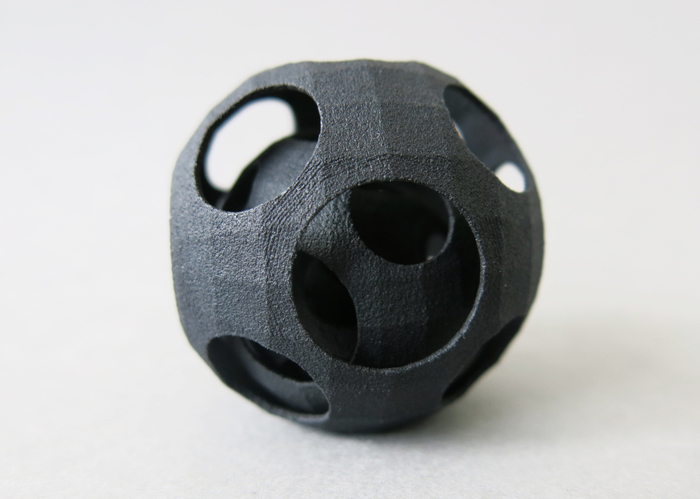
Right after the 3D printing process, the material is quite smooth itself and comes in grey color, as shown in the pictures of this blog post. Since this color option is not available on the website, you can contact our sales department for arranging color customisation of your order. You can also make great black plastic parts with it, as the parts can be further dyed in black. If you want to get more detailed information on the technical specifications of HP Multi Jet Fusion PA12 material, you can read this material data sheet.
HP Multi Jet Fusion PA12 3D printing material
Design guidelines for 3D Printing
HP Multi Jet Fusion can create complicated and highly detailed designs in a very short amount of time. HP Multi Jet Fusion plastic is great material for both an inexperienced designer and an experienced professional because of its high precision and low cost.
If you are not an experienced professional though, don’t worry. We will help you achieve the best 3D printing result!
Below we will go through some design guidelines that are necessary to keep in mind when designing a part that you will 3D print with the HP Multi Jet Fusion technology.
Design tips #1: Size limitations
First, the most important guideline is the size of your 3D model.
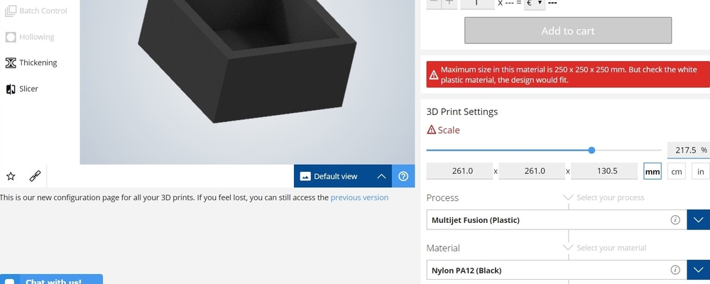
In general, when designing, keep in mind that the maximum size is limited by the physical size of the 3D printer. For this technology, the maximum volume that your part may have is 250×250×250 mm. If you need to build something larger, you’ll have to print your design in several parts and assemble it later. On our online platform where you upload your 3D file, you can scale your model to fit the size you want it to be.
In case your part is too big, you will get an automatic notification about it and you will be asked to rescale it to fit the volume limit, as you can see on the image below:
Design tips #2: Minimum thickness
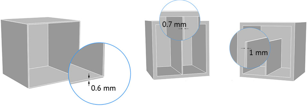
It is of high importance to consider the minimum thickness limitation, so as to ensure that your structure does not contain fragile details that might break. In the case of HP Multi Jet Fusion technology, the minimum wall thickness is 0.6 mm. With this value your design will be slightly flexible. To obtain more rigidity, you can choose a 2 mm wall thickness.
If the walls of your model are less than 0.6 mm, you can add a support structure to maintain stability. A stemmed element is a design aspect which is at least twice as long as it is thick. For unsupported and stemmed elements or parts of the design with a particular design constraint, it is also important to assign a minimum thickness of 0.9 mm in order to guarantee that the object will not break. Also, the minimum wall thickness for particular design aspects should be between 1 and 2 mm, as illustrated in the picture below.
On our online platform when you upload your 3D file, you can check the solidity of your model with our online solidity check tool. Depending on how thick or not your part is, it will be colored accordingly. The image below shows how it looks like:
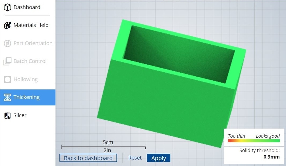
This particular object does not require any thickening, but what if your 3D model does? In this case, you will be asked to adjust the thickness of your parts in order to comply with the limitations. For these cases, we prepared a video for you that includes step by step guidelines about how to detect and thicken the fragile parts of your 3D model, if necessary.
Design tips #3: Proper geometry
3D printing indeed enables the creation of every kind of geometry. If you are not particularly familiar though with the technology that you are using, it is better to go safe. Meaning that, you can create a complex design, but keep in mind that if there is a very thin aspect that is supporting something that is too heavy for it, it may break. For this reason, it is better that you add manually a support structure to maintain stability. Particularly, we recommend adding a bit of thickness to the places that will get a lot of handling, or that support the object’s weight. These cases are illustrated in the following picture.
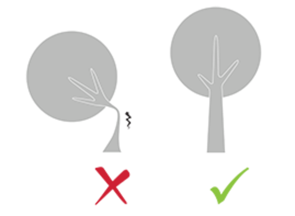
Sculpteo solidity check online tool does not detect physical aberrations such as floating parts, unstable position, parts supporting too much weight relative to its thickness, etc. So, you must be careful with the geometry of your design and the most stressed parts must be thickened.
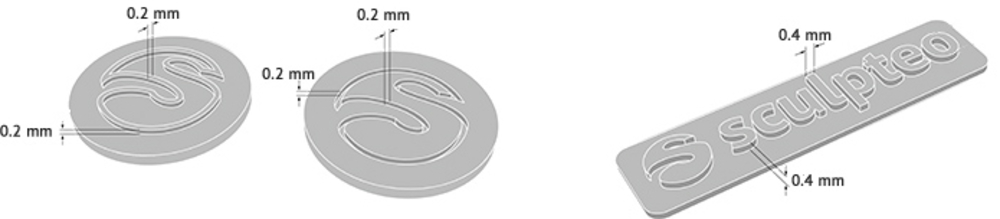
Design tips #4: Minimum engraving and depths
It is possible to engrave your 3D model. Though, keep in mind that if the design of your engraves are too detailed, they might not be visible due to the excess of powder that cannot be cleaned out. For this reason, we recommend that while designing your part, you design for a depth limit of at least 0.2 mm. In addition, if you want to add some text on your design, make sure that you will keep-up with at least 0.4mm of height and width. The image below, illustrates the instructions mentioned above:
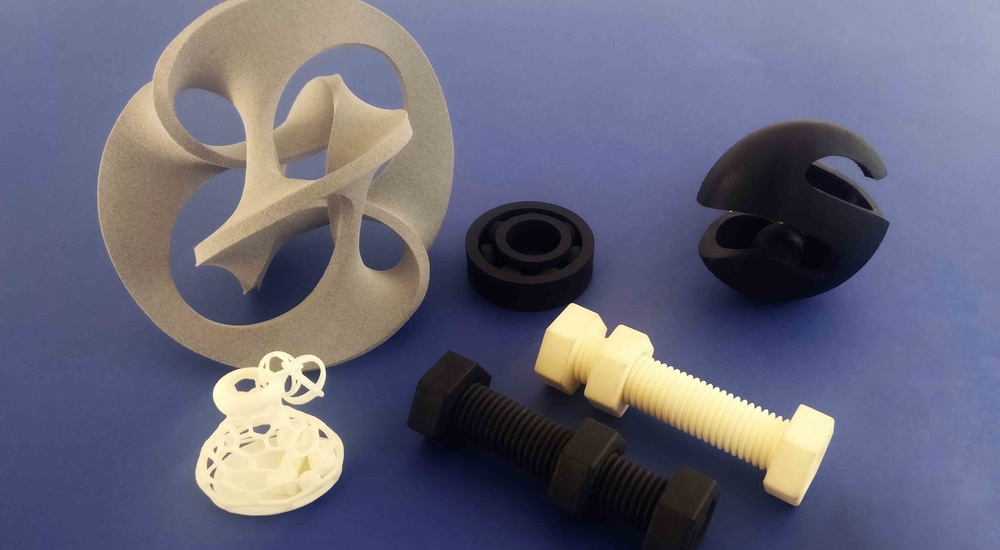
Design tips #5: Complexity of geometries
One of the best attributes of our Multi Jet Fusion PA12 material is its ability to print the most complex designs. Since this technology does not require external support material that has to be post-processed to be removed, you can create complex geometries, internal channels inside your part, built-in interlocked objects that require no assembly and can’t be disassembled. That said, you have infinite freedom in your design and you can create an object that couldn’t be created using traditional manufacturing techniques. Complex geometries like the ones described above are illustrated in the following picture.
When talking about complex geometries though, you should be careful about respecting the minimum clearance between the fixed walls or the articulated parts. This is essential to remove the excess of powder during post-processing, and guarantee that your object will have the ability to move and not become one solid volume. That said, we advise you to design your parts with a clearance of at least 0.5mm. Depending on the size of your object, you may need to modify this parameter. The bigger the object, the higher the indicated number should be. That is because the larger the object, the more time it will be exposed to high temperature. If the space left between the walls is too small, the walls will come in contact and adhere to each other due to heat spreading.
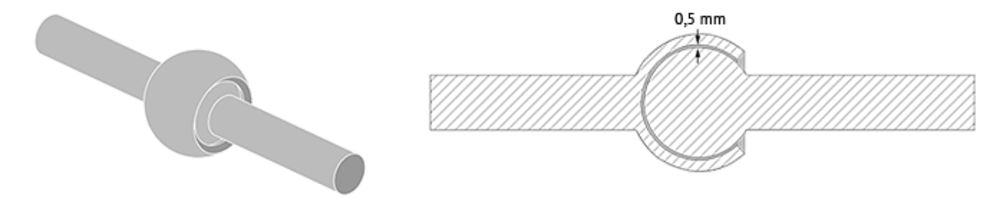
The exact same rule applies to the parts that need to be assembled after the 3D printing process. The minimum value of the space that two parts should have in order to be joined together should be set at least 0.5 mm.

Design tips #6: Hollowing parameter
Hollowing is needed as it serves as the drain for the excess of powder material within the object, as it is shown in the picture below.

It is recommended that you hollow your object manually, while designing in your 3D modeling software. The minimum size of these holes is determined by our website and has the ability to reduce the price of a 3D print by reducing the amount of material used.
The following video demonstrates the way this hollowing tool is working.
If you are looking for deeper knowledge regarding the material HP Multi Jet Fusion technology is using, feel free to browse its material page with all the related information, or even this article about HP PA12 black plastic. Now that you know everything about designing for HP Multi Jet Fusion technology, it’s time to test your knowledge. Since recently we upgraded our print page in order to provide you better customer experience, it will be easy now for you to upload your 3D file, and see your creation 3D printed in plastic with our HP Multi Jet Fusion technology. Start testing it now!